EasyMarker
Automatic video-based elements positioning

Automatic video-based elements positioning


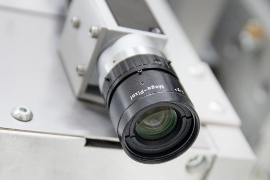
The first step is to mount the camera on the machine head and connect it to the computer. Camera should point down (along Z axis), but X and Y axes don't need to be aligned with machine X and Y axes.

In majority of cases, default module settings allow to start using the module right away. In other cases, the vision parameters can be tweaked to work in non-typical environment conditions (like underexposed or overexposed rooms).

It consists of choosing marker type, safe Z fly height and automatic recognition of calibration board.

After loading a file with elements to cut/machine and placing the material with printed elements and markers anywhere in the machine work area, all you need to do is to hover camera over first marker and push the START button! The module will automatically recognize all the markers and then the project will be adapted so that all the elements in the project will perfectly align with printed elements.
And be up-to-date with our CNC software and services. We will notify you when something new is out, so you won’t miss it.
+48 880 366 728